
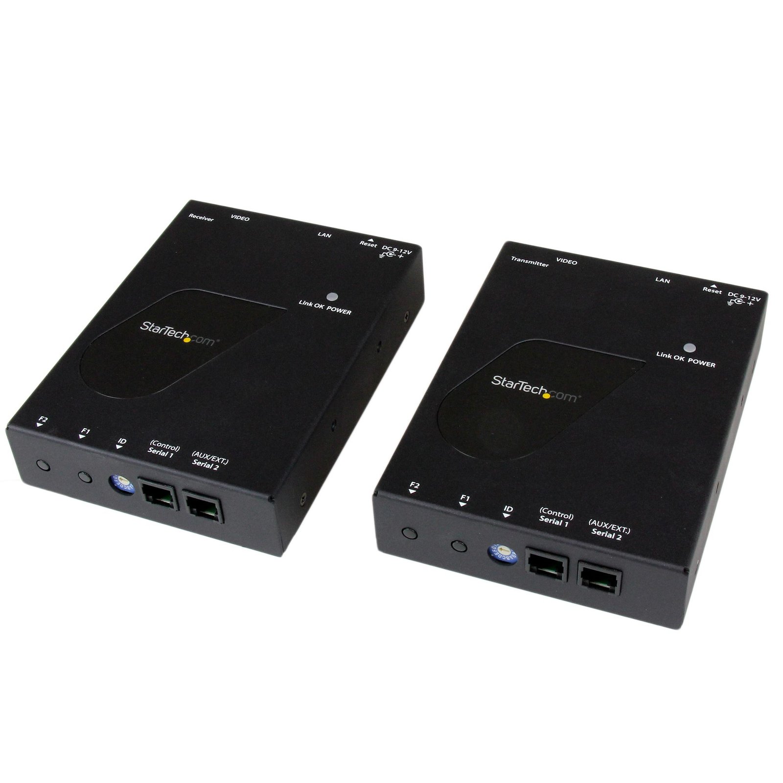
HDMI over IP distribution kit - 1080p - REPLACED BY ST12MHDLNHK - TAA
$240.99
Deploy content for digital signage through a scalable distribution system with intuitive control that’s ideal for point-to-point or video wall applications
Specifications & Compliance
- UPC
- 065030850759
- Brand
- StarTech.com
- Included in Package
- 1 - HDMI over IP transmitter, 1 - HDMI over IP receiver, 2 - mounting brackets, 2 - universal power adapter (NA / EU / UK / AU), 2 - foot pad set, 1 - instruction manual
- Shipping (Package) Weight
- 4.5 lb [2.0 kg]
- Weight of Product
- 33.1 oz [939.0 g]
- Product Length
- 5.1 in [13.0 cm]
- Product Width
- 3.8 in [97.0 mm]
- Product Height
- 1.1 in [28.0 mm]
- Package Depth
- 11.6 in [29.5 cm]
- Package Width
- 9.7 in [24.6 cm]
- Package Height
- 3.4 in [86 mm]
- Color
- Black
- Warranty
- 2 Years
- Connector 1
- HDMI
- Connector 1 (Quantity)
- 1
- Connector 2
- RJ-45
- Connector 2 (Quantity)
- 1
- Operating Temperature
- 0°C to 40°C (32°F to 104°F)
- Storage Temperature
- -10°C to 60°C (14°F to 140°F)
- Humidity
- 0% - 80 %
- Material
- Aluminum
- Power Source
- AC Adapter Included
- Input Voltage
- 100 - 240 AC
- Output Voltage
- 12V DC
- Connector 3
- RJ-45
- Connector 3 (Quantity)
- 1
- Power Consumption
- 10
- LED Indicators
- 1 - Link OK / POWER - Transmitter, 1 - Reset - Transmitter, 1 - Link OK / POWER - Receiver, 1 - Reset - Receiver
- Number of Ports
- 1
- Input Current
- 0.6 A
- Output Current
- 1.5
- Maximum Digital Resolutions
- 1920x1200 @60Hz
- Host Connector 1
- HDMI
- Host Connector 1 (Quantity)
- 1
- Audio
- Yes
- Plug Type
- M
- Center Tip Polarity
- Positive
- Connector 4
- HDMI
- Connector 4 (Quantity)
- 1
- Wide Screen Supported
- Yes
- Supported Resolutions
- 1920 x 1200 (1080p)
- Host Connector 2
- RJ-45
- Host Connector 2 (Quantity)
- 1
- Cascadable
- Yes
- Rack-Mountable
- No
- Max Distance
- 100m [328ft]
- Cabling
- Cat 5e UTP or better
Questions & Answers
How do I create a video wall with my ST12MHDLAN?
To create a video wall with ST12MHDLAN, do the following: Obtain the StarTech.com Video Switching & Wall Control app from the Google Play™ store or the App Store. Use multiple receivers (for example, ST12MHDLANRX) in conjunction with multiple transmitters to create the video wall. Use a wireless network infrastructure (for example, a wireless access point) in conjunction with a managed switch. Make sure that your mobile device is connected to the same network as the ST12MHDLAN. Note: The video wall cannot be created with switches that are not managed. For more information about why a managed switch is required, visit http://www.startech.com/faq/video_extenders_st12mhdlan_video_wall_network_requirements . A layer two managed Gigabit Ethernet switch ( IES101002SFP ) is recommended for use in video wall setups. The following example describes how to create a 2 x 2 video wall that uses two video inputs. The information contained in the example can be applied to setups with multiple switches, receivers, and transmitters. Hardware The following is a list of the hardware components used in the example setup: Two of the ST12MHDLAN . Two of the ST12MHDLANRX . One of the IES101002SFP . CAT 5e (or greater) Ethernet cables. HDMI ® cables. Four HDMI displays. Two HDMI sources (for example, computers). A computer that is connected by wired Ethernet. A mobile device that is running Android™ or iOS ® , and has the StarTech.com Video Switching & Wall Control app installed on it. Configure the hardware Use the Ethernet cables to connect the transmitters and receivers to the IES101002SPF. Connect the IES101002SPF to the rest of the network. Use the HDMI cables to connect the receivers to the displays. Use the HDMI cables to connect the HDMI sources to the transmitters. Set the thumbwheel to A on one transmitter. Set the thumbwheel to A on all of the receivers. Set the thumbwheel to B on the remaining transmitter. When all of the units are powered on and the HDMI sources are transmitting video, there should be mirrored images from source A displayed on the monitors. Configure the switch Note: The following instructions are based on the default configuration for the IES101002SFP switch. To access the configuration settings for the switch, complete the following: Use an Ethernet cable to connect a computer to one of the ports. Make sure that your computer's network adapter is on the same network as the network switch (by default, 192.168.2.XXX). For more information on how to change your IP address, refer to the following FAQ: https://www.startech.com/en-us/support/faqs/technical?topic=networking#ip-address-change-windows-mac-os . To configure the IGMP on the switch, complete the following: Use your web browser to navigate to 192.168.2.1 . The default login is Username = admin, Password = [blank]. To access the IGMP Snooping Configuration screen, click Configuration > IPMC > IGMP Snooping > Basic Configuration . In the Global Configuration settings, do the following: Select the Snooping Enabled check box. Select the Unregistered IPMCv4 Flooding Enabled check box. In the IGMP SSM Range field, type 232.0.0.0 /8 . Select the Leave Proxy Enabled check box. Select the Proxy Enabled check box. In the Port Related Configuration settings, do the following: Clear the Router Port check box. Select the Fast Leave check box. Set Throttling to Unlimited. Click Save . In IGMP Snooping , click VLAN Configuration . Click Add New IGMP VLAN . In the VLAN settings, do the following: Set the VLAN ID settings to 1 . Select the Snooping Enabled check box. Select the IGMP Querier check box. Set the Compatibility to IGMP-Auto . Set the RV to 2 . Set the QI (sec) to 125 . Set the QRI (0.1 sec) to 100 . Set the LLQI (0.1 sec) to 10 . Set the URI (sec) to 1 . Click Save . Connect your Android device to the network To connect to the network for the ST12MHDLAN, you need to connect your mobile device to the 169.254.XXX.XXX network. Depending on the version of the Android operating system that you are running, you many need to manually create a wireless network with a static IP address or assign an IP address for an existing wireless connection. To connect to the ST12MHDLAN network on a device running Android 5.1.1 (Lollipop) or Cyanogen 12.0, do the following: Make sure that the StarTech.com Video Switching & Wall Control app is installed on your device. Click Settings > WiFi . If you are or were connected to the wireless access point that you want to connect to, select that network and click Forget . Select the wireless network, and if required, enter your password. Click Advanced Options . Change the IP Settings to Static , and enter the following information: In the IP Address field, enter 169.254.XXX.XXX where XXX is a number between 2-254. Set the Gateway to default . Set the Network prefix length to 16 . Set the Other settings to default . Connect your iOS device to the network Click Settings > WiFi . Select the wireless network, and if required, enter your password. Click the blue arrow or i next to the network. Click the Static tab. Change the IP Settings to Static , and enter the following information: In the IP Address field, enter 169.254.XXX.XXX where XXX is a number between 2-254. Set the Subnet Mask to 255.255.0.0 . Set the Router to blank or your default gateway. Set the DNS to 8.8.8.8 . Configure the video wall You should now be able to detect two transmitters and four receivers in the Android application. The inputs can be routed and divided between the receivers and the positioning can be changed to achieve the necessary video wall configuration. You can disconnect the mobile device from the setup and the setup will retain the configuration as long as the video inputs remain turned on.
What are the best practices for setting up an HDMI extender?
Answer: For the best performance, ensure that all devices in the HDMI signal path are compatible, use high-quality cabling, minimize the number of adapters and converters, and follow the installation guidelines for the HDMI extender. Explanation: Following these best practices can help maximize signal quality, improve reliability, and reduce compatibility issues when deploying an HDMI extender. Verify HDMI compatibility. Ensure that the source device, HDMI extender, and display all support the required HDMI features, such as resolution, refresh rate, HDR, HDCP, or 3D, if applicable. Minimize signal conversions. Use the fewest possible adapters, splitters, switches, and converters. Each additional device increases the possibility of signal loss, compatibility issues, or HDCP handshake failures. Choose an extender with sufficient range. Select an HDMI extender that supports a maximum transmission distance greater than the distance required for your installation to provide additional performance margin. Use high-quality network cabling. For CAT5e, CAT6, or CAT6a HDMI extenders, use cable that meets or exceeds the extender's specifications and has been properly tested. Maintain consistent network wiring. Ensure that all network cables, patch panels, wall jacks, and keystone jacks use the same wiring standard (T568A or T568B) throughout the installation. Avoid unnecessary cable stress. Keep network cable runs as straight as practical and avoid tight bends, excessive coiling, or cable damage. Reduce electrical interference. Route network cables away from sources of electromagnetic interference (EMI), such as fluorescent lighting, motors, transformers, and power cables. Provide proper grounding. Ensure that connected equipment is properly grounded to help reduce electrical noise and improve system stability. Following these recommendations helps maximize video quality, maintain reliable HDCP communication, and improve the overall performance of an HDMI extender installation.
I want to use multiple transmitters on a network. How should I set the dip rotary switches?
If you wish to use multiple transmitters on a network, each Transmitter will need to be set to a different dip rotary switch value (0-9, A-F). Each Receiver will then need to match the transmitter it will be associated with. Note: changes to the dip rotary switches take effect after the transmitter(s) and receiver(s) are power-cycled.
I’m not seeing a video signal on the display. How do I fix this?
The power adapter may not be connected at the correct unit or may not be connected at all. Please check your product manual to see where your power adapter has to be positioned. An adapter to another video signal may be connected to the Transmitter or Receiver unit. Please avoid any converters for the initial setup. The Cat 5 or 6 cable coming from the transmitter or receiver unit may be connected to a network switch. Some of our video extenders will work in this configuration, but others will not. Please check your product manual to see if your model can be used connected to an IP network. For the initial setup, avoid connecting the Cat 5 or 6 cables to any network switch, hub, or router. The category of Unshielded Twisted Pair (UTP) cables may not meet StarTech.com’s requirements. Ensure at least Cat 5, 5e, or six cables are used, and they have eight wires. Some Cat 5 cables only have four wires. If using Cat 6 cables, be aware they have more twists per foot, so you may have to use shorter cable lengths if using Cat 6 cabling between your video extenders. Bundling up the UTP cabling connected to the extenders can cause crosstalk, which will prevent the video signal from showing on the display. Unwrapping the cable should resolve this issue.
The video signal is displayed, but the quality is not very good, or the colors are not accurate. How do I fix this?
Please check to see if your model has an adjustable Gain dial on the remote unit. If it does, use it to adjust the color until it is acceptable. Replace the VGA cable with a higher quality cable like StarTech.com’s MXT101MMHQ.
Everything is hooked up but nothing is working. What should I do?
When you troubleshoot issues with a video extender, there are some quick tests that you can complete to rule out potential problems. You can test to make sure that the following components are working correctly and are not the source of the issue: Video and Ethernet cables Video extender Video source (such as a DVD player or computer) Video destination (such as a monitor or projector) Note: When you are testing setup components, you should avoid using video adapters. For example, if you are converting a VGA source to HDMI for use with an HDMI extender, you should use an HDMI source when you test the components. To test your setup components, try the following: Use the cable, video extender, video source, and video destination in another setup to see if the problem is with the components or the setup. Use a different cable, video extender, video source, and video destination in your setup to see if the problem persists. Ideally, you should test a component that you know works in another setup. When you test your cables, it is recommended that you do the following: Test each cable individually. Use short cables when you are testing. When you test the video source and video destination, it is recommended that you do the following: Remove the video extender from your setup and test to make sure that the video source and video destination work together without the video extender. Test to make sure that the video source and video destination work together at the resolution that you want to use. Note: In order for your setup to work properly, the video source, extender, and destination all need to support the resolution that you are using.
How do I use the software application for this video extender?
The ST12MHDLAN app is available for iOS, Android, and Google Chrome. To download and install the app navigate to the StarTech.com website. You will find a download link for each platform on the ST12MHDLAN product page under the Overview tab. The device on which you install the application will be referred to as the control device. The control device must be on the same network as your ST12MHDLAN transmitters and receivers. The transmitters and receivers have a default IP address in the range of 169.254.x.x with a subnet mask of 255.255.0.0. If you need to change the IP address to fit your network infrastructure, make sure you keep all devices on the same network. For example, you can change your transmitter to 192.168.1.100 and your receiver to 192.168.1.101. There are links in the description to assist you in changing your control device's IP address. The app will automatically discover any transmitters and receivers that are on the same network as the control device. These devices will be shown in the Devices tab. You can manually force the control device to search for any transmitters and receivers by pressing the Refresh button in the Devices tab. You can access the Menu from any tab within the app. The menu includes a helpful guide to the app as well as the ability to search a specific IP address for a transmitter or receiver. The Menu also allows you to turn on Demo Mode which populates the app with virtual devices, allowing you to test configurations as if actual devices were connected. The Menu also includes Device Administration which you can use to reboot all of your connected devices or reset the connected devices to factory defaults. On the Devices tab you can adjust the individual settings for each transmitter and receiver. Simply tap on a device’s name to load that device’s settings. On the Settings page you can change the name of the device, the IP address and subnet, view error history, and other advanced settings. The second tab of the ST12MHDLAN app is the Switches tab. This tab allows you to define which video source is being sent to each video receiver. You can change the video source quickly and easily by selecting a different source in this tab. The final tab in the ST12MHDLAN app is titled Walls and allows you to customize your video walls and digital signage. To create a new video wall, complete the following: Tap the + icon. Under Wall Name enter a name. Assign the video wall a number of rows and columns. Tap Next . Assign a receiver to each of the displays in your video wall. You can tap on a display to change the receiver assigned to that display. (Optional) Correct for the bezel compensation. a)Tap Bezel Compensation . b)Measure your display with and without the bezel, and enter the measurements as indicated in the diagram above. Tap Save . As you add more video walls to the Walls tab you can easily modify or delete them by tapping on each entry. You can manage your video wall in one of two ways: On the Walls tab, tap a video source to select it for a video wall. On the Switches tab, tap a video source to select it for each display. If at this point you have questions about the ST12MHDLAN review the other videos in this series. If you would like to learn more about video extenders in general review our video series on that subject.
How do I calculate the average bandwidth this device uses?
To calculate the amount of bandwidth that this devices uses in Mbps at the maximum resolution of 1920x1080 @60Hz, add the number of transmitters to the number of receivers, and multiply the result by 45.
How do I change my IP address in Android OS?
Tap the Settings app. Tap Wi-Fi . Touch and hold the network that you want to set the IP address for. Tap Manage network settings . Note: Depending on the type of smartphone you are using and the version of the Android OS you are running, the text you see in step 4 might differ from Manage network settings . Select the Show advanced options check box. Under IP settings , tap the drop-down box. Tap Static . Enter the new IP address. If necessary, repeat step 8 for the gateway. Tap Save . To change your IP address so that you can access a specific device, complete steps 1 to 6, then tap DHCP to access the Internet again.
How do I change my IP address in Chrome OS?
Open Google Chrome . Click the Menu button. This button is indicated by three horizontal lines or three dots stacked on top of each other. Click Settings . Under Internet connection click twice on the network you want to set the IP address for. Click the Network tab. Uncheck the Configure automatically checkbox. Under IP address: enter the new IP address. If necessary, repeat step 7 for the Subnet mask and the Gateway . Click Close .
How do I change my IP address in iOS?
Click the Settings icon. Click Wi-Fi . Next to the name of the Wi-Fi network that you want to set the IP address for, click the blue i . Click the Static tab. In the IP Address field, enter the new static IP address. If necessary, repeat steps 4 and 5 for the Subnet Mask and Router fields. To save the changes, click the Wi-Fi networks icon. Note: If you are changing your IP address to access a specific device, repeat steps 1 to 3, and then click the DHCP tab to access the Internet again.
When should I use a longer video cable instead of a video extender?
Use a longer video cable whenever possible; use a video extender only when the required distance exceeds the reliable limits of standard or active cables. Explanation: Direct cabling is the preferred method for video connections because it maintains signal integrity and reduces complexity. Standard maximum cable lengths for common video signals are: Video standard Maximum length DisplayPort 50 ft. (15.2m) HDMI 50 ft. (15.2m) DVI 50 ft. (15.2m) VGA 200 ft. (71m) Active cables can extend these distances by incorporating built-in signal amplification and are designed to exceed standard length limits while maintaining specified performance. Video extenders are used when cable length requirements exceed what passive or active cables can reliably support. Extenders transmit the signal over longer distances by boosting and then restoring it, while maintaining the same video standard from input to output.
What is the correct way to convert and extend a video signal?
Convert the video signal as close to the source as possible, then extend the converted signal using a compatible video extender. Explanation: When both signal conversion and extension are required, the conversion should occur before the signal is extended. Placing the video converter near the source device ensures the signal is converted to the desired format early, which improves compatibility and signal stability over long distances. After conversion, a video extender should be used to transmit the signal over the required distance while maintaining the same video standard end-to-end. For example, to send a VGA signal to a distant HDMI display, first convert VGA to HDMI at the source, then use an HDMI extender to carry the signal to the display. This approach minimizes signal degradation and ensures the extender operates with a consistent signal type throughout the transmission.
What is a StarTech.com HDMI over IP video extender, and what requirements must my network meet for it to work?
A StarTech.com HDMI over IP video extender transmits HDMI video and audio over an IP network, and it requires sufficient network bandwidth, IGMP support, and standard Ethernet connectivity to function correctly. Explanation: A StarTech.com HDMI over IP video extender converts HDMI video and audio signals into IP packets and distributes them across an existing Ethernet network. This enables scalable video distribution, including video wall configurations and multi-display setups, unlike point-to-point extenders that rely on direct cabling or wireless links. To determine compatibility, the network must meet the following requirements: Ethernet connectivity and distance: Each transmitter and receiver must connect to a network switch or router using standard Ethernet cabling, with a maximum distance of 100 meters per device-to-switch link. Network bandwidth capacity: Video streams consume network bandwidth. For 1080p at 60 Hz, calculate required bandwidth as: (number of transmitters + number of receivers) × 45 Mbps. For example, 1 transmitter and 4 receivers require approximately 225 Mbps. A Gigabit Ethernet network is recommended to maintain performance and stability. Scalability limits: The StarTech.com ST12MHDLAN supports up to 16 transmitters, depending on available network bandwidth. The number of receivers is also constrained by total network capacity. IGMP support: The network switch or router must support Internet Group Management Protocol (IGMP) to efficiently manage multicast traffic between transmitters and receivers. C ontrol software compatibility: Supported StarTech.com video extender models include a free management application (iOS, Android, and Google Chrome) for automatic device detection, video wall configuration, and source switching. Optional USB extension: Some StarTech.com HDMI over IP video extender models also support USB signal extension alongside video and audio distribution. Meeting these requirements ensures reliable operation, predictable performance, and scalable deployment across multiple displays and endpoints.
What are the network and setup requirements for using a StarTech.com video extender in a video wall configuration?
A StarTech.com video extender requires a managed network switch with IGMP support, sufficient network bandwidth, and proper multicast configuration to operate in a video wall setup; unmanaged switches do not support video wall configurations. Explanation: A StarTech.com video extender can operate in point-to-point, mirror, or video wall configurations, but video wall setups have specific network and configuration requirements: Managed switch with IGMP support: A managed network switch that supports Internet Group Management Protocol (IGMP) is required for any video wall or multi-transmitter setup. IGMP controls multicast traffic so that video streams are delivered only to intended receivers. Without IGMP, video wall configurations will not function correctly. Multicast traffic management: IGMP-enabled switches automatically detect and manage multicast group memberships between transmitters and receivers. During initialization, the switch may take up to one minute to learn the network topology and optimize traffic routing. Network bandwidth requirements: The network must have enough capacity to handle all active video streams. Insufficient bandwidth can cause dropped frames, latency, or connection timeouts during video wall operation. Unmanaged switch limitations: Unmanaged (plug-and-play) switches do not support IGMP and cannot control multicast traffic. They are limited to single-transmitter mirror mode only and will cause network congestion or timeouts if used for video wall configurations. Point-to-point configuration: A direct Ethernet connection between one transmitter and one receiver does not require a network switch. Both units must have matching thumbwheel settings to communicate on the same default network. Video wall scalability: Multiple transmitters and receivers can be combined in a video wall layout only when the network infrastructure supports IGMP and sufficient bandwidth for all streams. These requirements ensure reliable multicast video distribution, prevent network flooding, and enable stable, scalable video wall deployments using StarTech.com video extenders.
Is a StarTech.com video extender compatible with set-top boxes, and what are the requirements?
Yes, a StarTech.com video extender is compatible with set-top boxes if the set-top box is HDCP-compliant and allows intermediary devices between the source and display; otherwise, it will not work. Explanation: A StarTech.com video extender can transmit video from a set-top box to a remote display, but compatibility depends on the set-top box’s signal protection and connection requirements. HDCP compliance required: The set-top box must support High-bandwidth Digital Content Protection (HDCP) in a way that allows video output through external devices. If HDCP implementation blocks transmission through intermediary hardware, the video extender will not display content. Intermediary device support required: The set-top box must allow a device, such as a video extender, to be placed between the source and the display. Some set-top boxes require a direct HDMI connection and will not output video through any intermediate device. If the set-top box does not meet both requirements, the StarTech.com video extender will not function correctly with that device.
How many transmitters and receivers can I connect to a StarTech.com video extender, and what are the limits?
A StarTech.com video extender supports up to 16 transmitters, and the number of receivers is not fixed but is limited by available network bandwidth. Explanation: A StarTech.com video extender allows multiple transmitters and receivers on the same network, but overall system capacity depends on both device limits and network performance. Maximum transmitters: The system supports up to 16 transmitters. This is a hard limit, but actual performance depends on available network bandwidth. Receivers are bandwidth-limited: There is no fixed maximum number of receivers; however, each receiver adds additional bandwidth usage. The total number of receivers is therefore constrained by network capacity. Bandwidth impact: Each active transmitter and receiver contributes to total network load. If bandwidth is insufficient, video performance may degrade, and other network devices may be affected. A StarTech.com video extender system will not scale reliably beyond network capacity, even though receiver count is not explicitly capped.
What is IGMP, and why is IGMP required for a StarTech.com video extender?
IGMP (Internet Group Management Protocol) is a network protocol that controls multicast traffic, and it is required for a StarTech.com video extender to ensure video streams are sent only to intended receivers instead of all devices on the network. Explanation: Internet Group Management Protocol (IGMP) is used by network devices, such as switches and routers, to manage multicast group membership. It ensures that network traffic is delivered only to devices that request it, rather than broadcasting it to every device on the network. A StarTech.com video extender relies on multicast transmission to distribute video streams efficiently across multiple receivers. IGMP is required for the following reasons: Targeted video distribution: IGMP ensures that video streams are sent only to designated receivers, not to all devices on the network. Reduced network congestion: Without IGMP, the video extender would flood the network with multicast traffic, sending video data to every connected device. Network performance protection: Excessive unnecessary traffic can degrade performance for other devices and applications on the network. If IGMP is not supported or enabled, a StarTech.com video extender may cause network congestion, reduced video performance, or failure to operate correctly in multi-device setups.
Can I mix or use ST12MHDLAN and ST12MHDLANU transmitters and receivers together?
No, StarTech.com ST12MHDLAN and ST12MHDLANU transmitters and receivers are not interchangeable and cannot be used together in the same setup. Explanation: StarTech.com ST12MHDLAN and ST12MHDLANU are separate video extender systems designed with different hardware architectures and communication protocols. No interoperability: Devices from the ST12MHDLAN series cannot communicate with devices from the ST12MHDLANU series. Model-specific compatibility required: Each transmitter must be used only with receivers from the same product model. Mixed systems not supported: Combining ST12MHDLAN and ST12MHDLANU devices in a single deployment will result in system failure or no signal transmission. To ensure proper operation, all transmitters and receivers in a StarTech.com video extender setup must belong to the same model series.
How much video delay or latency should I expect when using a StarTech.com video extender?
It depends; the video delay (latency) of a StarTech.com video extender cannot be fixed or guaranteed and varies based on network conditions and setup. Explanation: Video latency when using a StarTech.com video extender is influenced by multiple factors within the network and deployment environment, so it cannot be defined as a specific value or milliseconds range. Network bandwidth and congestion: Limited bandwidth or heavy traffic increases video delay. Network hardware performance: Switches, routers, and cabling quality directly affect transmission speed and latency. Number of transmitters and receivers: More connected devices increase total network load and can introduce additional delay. Network configuration and topology: Complex routing, multicast handling, and infrastructure design can impact latency. Because these variables differ across environments, a StarTech.com video extender may exhibit different levels of delay or lag in each installation, and latency cannot be accurately predicted in advance.
How can I connect this HDMI output to a VGA, DVI, or DisplayPort display?
An HDMI output can be connected to VGA, DVI, or DisplayPort displays using the appropriate adapter or video converter. The required solution depends on the input type of the display and whether HDCP-protected content is being used. Explanation: This device outputs HDMI video signals. If the display or video destination uses a different connection type, an adapter or active video converter may be required. Common conversion options include: VGA: An active HDMI to VGA converter is required because HDMI uses digital video signaling and VGA uses analog video signaling. DVI: A passive HDMI to DVI adapter or cable can be used because HDMI and DVI share compatible digital video signaling. DisplayPort: An active HDMI to DisplayPort converter is required because HDMI and DisplayPort use different signaling technologies. HDCP Considerations Before converting an HDMI signal, determine whether the source content is protected by High-bandwidth Digital Content Protection (HDCP). HDCP is commonly used by devices such as: Blu-ray players DVD players Streaming devices Gaming consoles If the HDMI source is transmitting HDCP-protected content, conversion to an analog video format such as VGA may not be supported because VGA does not support HDCP. In these situations, video may not display correctly or may not display at all. Best Practices For the most reliable results: Use the fewest possible adapters and converters. Verify the required resolution and refresh rate. Confirm that the converter supports the desired signal direction and video format. Consider HDCP requirements when converting protected content.
How can I connect a VGA, DVI, or DisplayPort video source to this device's HDMI input?
This device features an HDMI input. If your video source uses VGA, DVI, or DisplayPort, you can connect it using the appropriate adapter or video converter. The required solution depends on the video output available on the source device. Explanation: HDMI inputs require an HDMI signal. Video sources that use VGA, DVI, or DisplayPort may require signal conversion before they can be connected to this device. Common conversion options include: VGA source: Use an active VGA-to-HDMI converter because VGA uses analog video signaling and HDMI uses digital video signaling. DVI source: Use a passive DVI-to-HDMI adapter, cable, or converter. DVI and HDMI use compatible digital video signaling, making conversion straightforward in most applications. DisplayPort source: Use either a passive or active DisplayPort-to-HDMI adapter, depending on the capabilities of the DisplayPort source. DisplayPort Passive vs. Active Adapters When converting from DisplayPort to HDMI, the correct adapter type depends on whether the DisplayPort source supports DisplayPort Dual-Mode (DP++). Passive adapters require a DisplayPort Dual-Mode (DP++) source. Active adapters work with both standard DisplayPort and DisplayPort Dual-Mode (DP++) sources. If you are unsure whether the source supports DisplayPort Dual-Mode, consult the device documentation or use an active adapter for broader compatibility. For more information about converting DisplayPort video signals, refer to the following FAQ: https://www.startech.com/faq/DisplayPort_Converter_DP_Multi_Mode . For the most reliable installation: Use the fewest possible adapters and converters. Verify support for the required resolution and refresh rate. Confirm that the adapter or converter supports the correct signal direction.
What DC barrel connector power plug types do StarTech.com products use, and what are their dimensions?
StarTech.com DC barrel connector plug types are defined in the “Plug Type” field of the technical specifications, using a letter code that specifies the connector’s outer diameter (OD) and inner diameter (ID) in millimeters for power adapter compatibility. Explanation: In StarTech.com technical specifications, the “Plug Type” field is a standardized identifier for the exact DC barrel connector size required to power a product. Each plug type is assigned a letter code that corresponds to a specific combination of outer diameter (OD) and inner diameter (ID), measured in millimeters. Common DC barrel plug type dimensions Plug Type OD ID A 2.35 mm 0.7 mm B 4.0 mm 1.7 mm C 4.75 mm 1.7 mm H 3.4 mm 1.3 mm L 5.0 mm 2.5 mm M 5.5 mm 2.1 mm N 5.5 mm 2.5 mm The DC barrel connector plug type must match both the outer diameter and inner diameter exactly. A mismatch between the StarTech.com product requirement and the power adapter connector can prevent proper fit or stable power delivery, which may result in device startup failure or intermittent operation. The plug type defines only the physical connector size. The plug type does not define electrical power requirements such as voltage, current, or polarity. The power adapter used with a StarTech.com product must match the product’s specified electrical requirements. Using an incompatible power adapter can cause device malfunction or permanent damage. This standardized DC barrel connector plug type system enables IT professionals and procurement teams to verify connector dimensions, ensure power adapter compatibility, standardize hardware deployments, and identify the correct replacement power supply for StarTech.com products.
Related products
-
HDMI over CAT6 Extender - 4K 60Hz - 330 ft. (100 m) - TAA
$421.26 Add to cart -

4K HDMI Extender with Compact Transmitter - HDBaseT - UHD 4K - TAA
$357.71 Add to cart -

HDMI over CAT5e HDBaseT Extender - Power over Cable - Ultra HD 4K - TAA
$244.96 Add to cart -
HDMI over CAT5 HDBaseT Extender - Power over Cable - IR - RS232 - 10/100 Ethernet - Ultra HD 4K - 330 ft (100m) - TAA
$222.99 Add to cart