DVI Video Extender over Cat 5 UTP
$193.99
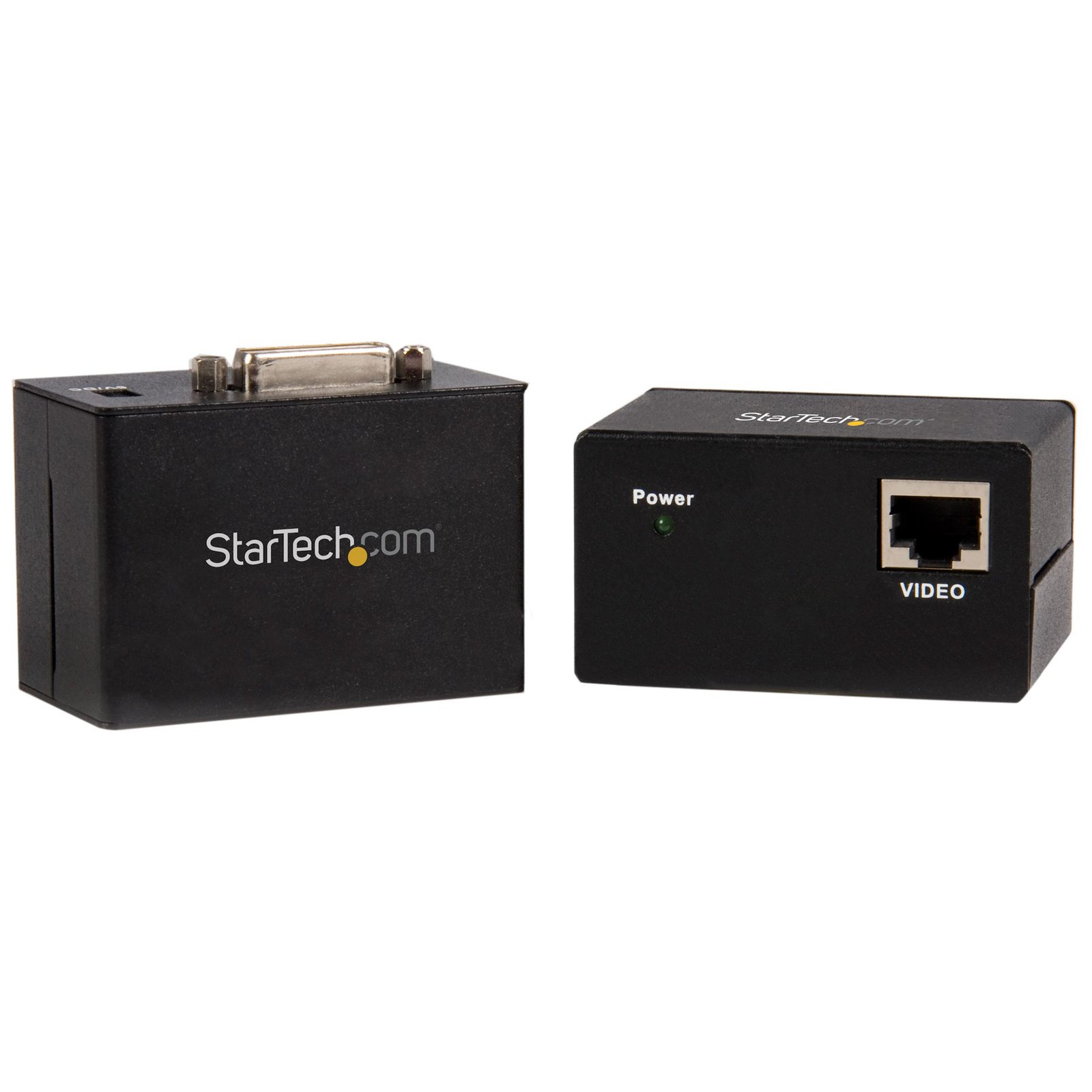
Extend a single DVI video signal up to 150ft over Cat5 cabling
Specifications & Compliance
- UPC
- 065030819848
- Brand
- StarTech.com
- Included in Package
- 1 - DVI Local Unit Extender, 1 - DVI Remote Unit Extender, 2 - Power Adapters, 1 - Instruction Manual
- Shipping (Package) Weight
- 22.6 oz [639 g]
- Weight of Product
- 10.1 oz [285.5 g]
- Product Length
- 2.6 in [67.0 mm]
- Product Width
- 2.0 in [52.0 mm]
- Product Height
- 1.5 in [38.0 mm]
- Package Depth
- 2.6 in [67 mm]
- Package Width
- 9.6 in [24.4 cm]
- Package Height
- 6.1 in [15.5 cm]
- Color
- Black
- Warranty
- 2 Years
- Connector 1
- DVI-I Dual-Link (29-Pin)
- Connector 1 (Quantity)
- 1
- Package Quantity
- 1
- Connector 2
- RJ-45
- Connector 2 (Quantity)
- 1
- Operating Temperature
- 32° to 122° F (0° to 50° C)
- Storage Temperature
- -4° to 158° F (-20 to 70° C)
- Humidity
- 15 to 90% relative humidity, non-condensing
- Material
- Steel
- Power Source
- 2 AC Adapters Included
- Special Notes
- DVI-A (Analog) signal not supported
- Input Voltage
- 100 - 240 AC
- Output Voltage
- 5 DC
- Power Consumption
- 5
- MTBF
- 180,102 hours
- Number of Ports
- 1
- Input Current
- 0.2A
- Output Current
- 1
- Maximum Digital Resolutions
- 1600x1200 @ 60Hz
- Host Connector 1 (Quantity)
- 1
- Audio
- No
- Plug Type
- H
- Center Tip Polarity
- Positive
- Host Connector 2
- RJ-45
- Host Connector 2 (Quantity)
- 1
- Cascadable
- No
- Max Distance
- 45m [148ft]
- Cabling
- Cat 5 UTP or better
Questions & Answers
How do I set up my video extender?
To set up a video extender, connect the transmitter to the video source, connect the receiver to the display, link the transmitter and receiver using the supported extension medium, and apply power if required. Explanation: Before installing the video extender, verify that you have all required components, including: Video transmitter Video receiver Video source (such as a computer or media player) Display (such as a monitor, projector, or television) Appropriate video cables Ethernet or fiber cable, if required by the extender Power adapter(s), if required Before deploying the extender in its final location, it is recommended to test the complete system using a simplified setup to confirm proper operation. To install the video extender: Place the transmitter near the video source. Connect the video source to the transmitter. Connect power to the transmitter, if required. Place the receiver near the display. Connect the receiver to the display. Connect power to the receiver, if required. Connect the transmitter and receiver using the required extension medium (such as Ethernet or fiber cable), if applicable. Connect any optional USB, audio, IR, RS-232, or other supported devices, if your video extender supports these features. If using a wireless video extender, pair the transmitter and receiver according to the product instructions. After installation, verify that the display shows the video output from the source device. If the video does not appear: Verify that all cables are securely connected. Confirm that the transmitter and receiver are connected using the supported cable type and distance. Verify that both units are powered, if external power is required. Confirm that the video source, display, resolution, and refresh rate are supported by the video extender. Refer to the product manual for model-specific requirements, supported cable distances, and optional features.
I’m not seeing a video signal on the display. How do I fix this?
The power adapter may not be connected at the correct unit or may not be connected at all. Please check your product manual to see where your power adapter has to be positioned. An adapter to another video signal may be connected to the Transmitter or Receiver unit. Please avoid any converters for the initial setup. The Cat 5 or 6 cable coming from the transmitter or receiver unit may be connected to a network switch. Some of our video extenders will work in this configuration, but others will not. Please check your product manual to see if your model can be used connected to an IP network. For the initial setup, avoid connecting the Cat 5 or 6 cables to any network switch, hub, or router. The category of Unshielded Twisted Pair (UTP) cables may not meet StarTech.com’s requirements. Ensure at least Cat 5, 5e, or six cables are used, and they have eight wires. Some Cat 5 cables only have four wires. If using Cat 6 cables, be aware they have more twists per foot, so you may have to use shorter cable lengths if using Cat 6 cabling between your video extenders. Bundling up the UTP cabling connected to the extenders can cause crosstalk, which will prevent the video signal from showing on the display. Unwrapping the cable should resolve this issue.
The video signal is displayed, but the quality is not very good, or the colors are not accurate. How do I fix this?
Please check to see if your model has an adjustable Gain dial on the remote unit. If it does, use it to adjust the color until it is acceptable. Replace the VGA cable with a higher quality cable like StarTech.com’s MXT101MMHQ.
Everything is hooked up but nothing is working. What should I do?
When you troubleshoot issues with a video extender, there are some quick tests that you can complete to rule out potential problems. You can test to make sure that the following components are working correctly and are not the source of the issue: Video and Ethernet cables Video extender Video source (such as a DVD player or computer) Video destination (such as a monitor or projector) Note: When you are testing setup components, you should avoid using video adapters. For example, if you are converting a VGA source to HDMI for use with an HDMI extender, you should use an HDMI source when you test the components. To test your setup components, try the following: Use the cable, video extender, video source, and video destination in another setup to see if the problem is with the components or the setup. Use a different cable, video extender, video source, and video destination in your setup to see if the problem persists. Ideally, you should test a component that you know works in another setup. When you test your cables, it is recommended that you do the following: Test each cable individually. Use short cables when you are testing. When you test the video source and video destination, it is recommended that you do the following: Remove the video extender from your setup and test to make sure that the video source and video destination work together without the video extender. Test to make sure that the video source and video destination work together at the resolution that you want to use. Note: In order for your setup to work properly, the video source, extender, and destination all need to support the resolution that you are using.
When should I use a longer video cable instead of a video extender?
Use a longer video cable whenever possible; use a video extender only when the required distance exceeds the reliable limits of standard or active cables. Explanation: Direct cabling is the preferred method for video connections because it maintains signal integrity and reduces complexity. Standard maximum cable lengths for common video signals are: Video standard Maximum length DisplayPort 50 ft. (15.2m) HDMI 50 ft. (15.2m) DVI 50 ft. (15.2m) VGA 200 ft. (71m) Active cables can extend these distances by incorporating built-in signal amplification and are designed to exceed standard length limits while maintaining specified performance. Video extenders are used when cable length requirements exceed what passive or active cables can reliably support. Extenders transmit the signal over longer distances by boosting and then restoring it, while maintaining the same video standard from input to output.
What is the correct way to convert and extend a video signal?
Convert the video signal as close to the source as possible, then extend the converted signal using a compatible video extender. Explanation: When both signal conversion and extension are required, the conversion should occur before the signal is extended. Placing the video converter near the source device ensures the signal is converted to the desired format early, which improves compatibility and signal stability over long distances. After conversion, a video extender should be used to transmit the signal over the required distance while maintaining the same video standard end-to-end. For example, to send a VGA signal to a distant HDMI display, first convert VGA to HDMI at the source, then use an HDMI extender to carry the signal to the display. This approach minimizes signal degradation and ensures the extender operates with a consistent signal type throughout the transmission.
How can I identify which DVI connector type I have or need?
You can identify the DVI connector type by the pin configuration and determine compatibility based on whether the connection supports analog, digital, or both signal types. Explanation: DVI (Digital Visual Interface) connectors are defined by their pin layout and supported signal type. The main DVI connector types are: DVI-A (17 pin) . Analog signal only DVI-D Single Link (19 pin) . Digital signal only DVI-D Dual Link (25 pin) . Digital signal only, higher bandwidth DVI-I Single Link (23 pin) . Supports both analog and digital signals DVI-I Dual Link (29 pin) . Supports both analog and digital signals, higher bandwidth DVI-A is used for analog signals (similar to VGA), while DVI-D is used for digital signals (similar to HDMI). DVI-I connectors can carry both analog and digital signals, but actual support depends on the device’s specifications. Single Link and Dual Link indicate bandwidth capacity, which affects maximum supported resolution. Typical limits are up to 1920 × 1080 @ 60 Hz for Single Link and up to 2560 × 1600 @ 60 Hz for Dual Link. However, actual resolution support depends on the capabilities of the connected devices, not just the connector type. To ensure compatibility, verify both the connector type and the signal support in the specifications of the source and display devices.
What is a video extender, and how can I tell if it will work in my setup?
A video extender (such as an HDMI extender or DisplayPort extender) transmits audio and video signals over longer distances than standard cables, and compatibility depends on signal type, bandwidth, resolution, distance, and cabling. Explanation: A video extender is a transmitter and receiver system that extends a video signal beyond standard cable limits by sending it over media such as Cat5e/Cat6 Ethernet, fiber optic cable, or wireless. Common types include HDMI extenders and DisplayPort extenders, often used for long-distance AV distribution. To determine if a video extender will work in a specific setup, verify the following: Signal compatibility: The extender must support the same video standard as the source and display (e.g., HDMI, DisplayPort) Resolution and bandwidth: Confirm support for required resolutions and bandwidth (e.g., 1080p, 4K, refresh rate, color depth) Distance and cable type: Ensure the extender supports the required distance over the intended medium (e.g., Cat6, fiber) Infrastructure type: Some extenders require direct point-to-point connections, while others (IP-based extenders) support network switches Latency requirements: Check latency specifications for real-time applications (e.g., gaming, AV control) Feature support: Verify support for audio, USB, IR control, HDCP, and EDID if needed Power requirements: Confirm power is available for transmitter and receiver units If the video extender does not match the signal type, bandwidth, or infrastructure, it may result in no signal, reduced resolution, increased latency, or unstable performance.
Can a StarTech.com point-to-point video extender be used through a network switch or router?
No, a StarTech.com point-to-point video extender cannot be used through a network switch or router; it requires a direct Ethernet connection between the transmitter and receiver. Explanation: A StarTech.com point-to-point video extender is designed to transmit video over a dedicated Ethernet link between two devices, not across a shared network. Direct connection only: The transmitter must connect directly to the receiver using a single Ethernet cable. No network device support: Network switches and routers are not supported and cannot be used in the signal path. Not network-based (non-IP): This type of video extender does not convert video into IP traffic and cannot operate over standard network infrastructure. If a switch or router is introduced between the transmitter and receiver, the StarTech.com video extender will not function.
How can I connect this DVI-I output to a VGA, HDMI, or DisplayPort display?
Although this device uses a DVI-I connector, it supports only digital DVI video signaling. The appropriate adapter or converter depends on the type of display connection you need to use. Explanation: This device features a DVI-I connector but does not output analog DVI-I signals. Instead, it supports only digital DVI signaling, similar to DVI-D. As a result: HDMI: A DVI to HDMI adapter or cable can be used because DVI and HDMI share compatible digital video signaling. DisplayPort: An active DVI to DisplayPort converter is required because DVI and DisplayPort use different signaling technologies. VGA: An active DVI-D to VGA converter is required because VGA uses analog video signaling and the device outputs only digital video. When selecting a conversion solution, use the fewest possible adapters and converters to maximize compatibility and simplify installation. Before purchasing a converter, verify: The input type of the display The required resolution and refresh rate Whether the converter supports active digital-to-analog conversion when connecting to VGA Although DVI-I can support both analog and digital signaling, some devices with DVI-I connectors may support only digital DVI-D signaling internally. Refer to the device specifications to confirm supported signal types.
What DC barrel connector power plug types do StarTech.com products use, and what are their dimensions?
StarTech.com DC barrel connector plug types are defined in the “Plug Type” field of the technical specifications, using a letter code that specifies the connector’s outer diameter (OD) and inner diameter (ID) in millimeters for power adapter compatibility. Explanation: In StarTech.com technical specifications, the “Plug Type” field is a standardized identifier for the exact DC barrel connector size required to power a product. Each plug type is assigned a letter code that corresponds to a specific combination of outer diameter (OD) and inner diameter (ID), measured in millimeters. Common DC barrel plug type dimensions Plug Type OD ID A 2.35 mm 0.7 mm B 4.0 mm 1.7 mm C 4.75 mm 1.7 mm H 3.4 mm 1.3 mm L 5.0 mm 2.5 mm M 5.5 mm 2.1 mm N 5.5 mm 2.5 mm The DC barrel connector plug type must match both the outer diameter and inner diameter exactly. A mismatch between the StarTech.com product requirement and the power adapter connector can prevent proper fit or stable power delivery, which may result in device startup failure or intermittent operation. The plug type defines only the physical connector size. The plug type does not define electrical power requirements such as voltage, current, or polarity. The power adapter used with a StarTech.com product must match the product’s specified electrical requirements. Using an incompatible power adapter can cause device malfunction or permanent damage. This standardized DC barrel connector plug type system enables IT professionals and procurement teams to verify connector dimensions, ensure power adapter compatibility, standardize hardware deployments, and identify the correct replacement power supply for StarTech.com products.